Reliability, Robustness, Thermal Shock/Cycling & Reflow Simulation Wrapped Up Into A Single System
Multiple Test Coupon Types
Test IPC-2221B Type "D" Daisy Chain, HATS² Single Via*, Solder Joint, Custom Coupons up to 7 Nets
Convection Reflow Simulation up to 265°C
Create Profiles That Match Your Reflow Ovens or Use the IPC-TM-650 Standard Profiles
Thermal Shock / Cycling -65°C & +265°C
High Speed Air Transfers Heat as Rapidly as Sample Mass & Thermal Conductivity Allow
Rapid Real Time Resistance Monitoring
Micro-Ohm Precision Measurements of both Single Vias and Daisy-chains
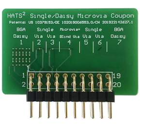
The HATS² Single Via Coupon*
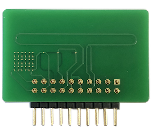
The HATS² Single Via Coupon* uses Patented Technology to allow accurate, high current, micro-ohm precision, 4-wire resistance measurement of 7 Single Via Structures or Daisy-chain test nets in a HATS² Test System. This allows accelerated Reliability, Robustness and Component Attachment Process Simulation testing to occur on low resistance test nets (<0.001 Ohm) in a HATS² Test System during temperature exposures between -65°C and 265°C. Click on the questions below the Test Coupon Examples to learn more about the HATS² Test System and Single Via Coupon*.
Your Questions Answered
Reflow, Reliability & Robustness
The HATS² Test System
A complete test system that gives you insight into the expected performance and reliability of the PCBs and Substrates going into your electronic products
Unlike other Accelerated Testing Techniques, HATS² Testing is performed by Licensed Service Laboratories around the world that carry ISO/IEC 17025, AALA and/or ITAR certifications. This provides the benefit of having a Professional Full-Service Test Laboratory with documented quality and calibration systems providing HATS² test services & results. These laboratories can also provide other test services to you (like Failure Analysis) to further understand your test coupons & results. Check to see if your current test service provider truly meets your ISO/IEC 17025, ITAR, quality system or calibration system requirements.
The Patented HATS² Single Via Coupon* can test 7 Individual Via Structures, Portions of Via Structures (between layers of subs) or Daisy-chained Via Structure Nets. This allows the HATS² Test System to collect electrical resistance data from BOTH Single Via Structures (or portions of via structures) and Daisy-chain test nets from a single test coupon. Designers can include 1 or 2 daisy-chain nets along with 5-6 single via structure nets on the same HATS² Single Via Coupon*. This should provide a bridge to historical Daisy-chain data and create opportunities to see the difference between single via structures and daisy-chain net test results.
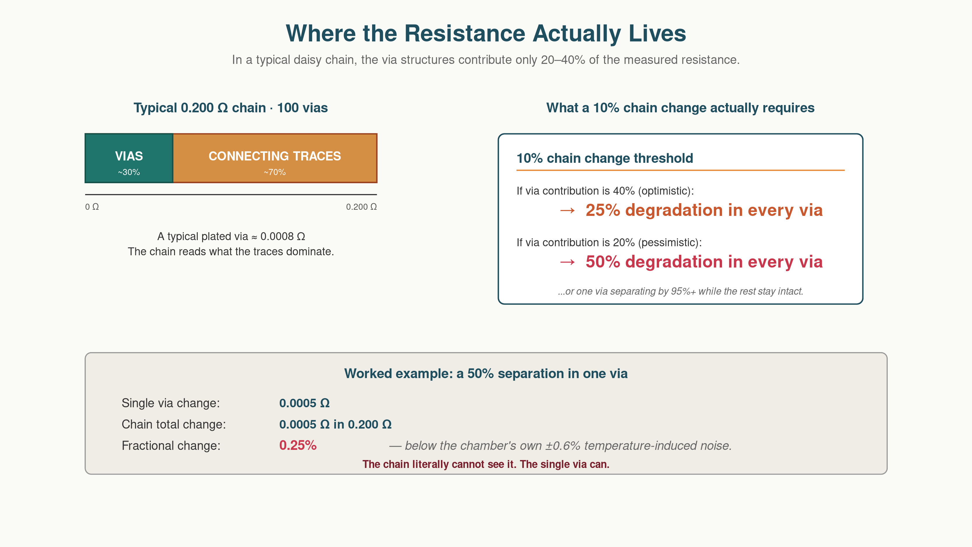
Multiple via structures daisy-chained together have historically been tested to assess via reliability, robustness or component attachment process (convection reflow) survivability in an attempt to obtain some sort of statistical significance in via sampling. The first issue encountered with daisy-chain testing of via structures is that depending on design, 70-90+% of the measured resistance comes from the circuit traces connecting the via structures together and not from the actual via structures themselves.
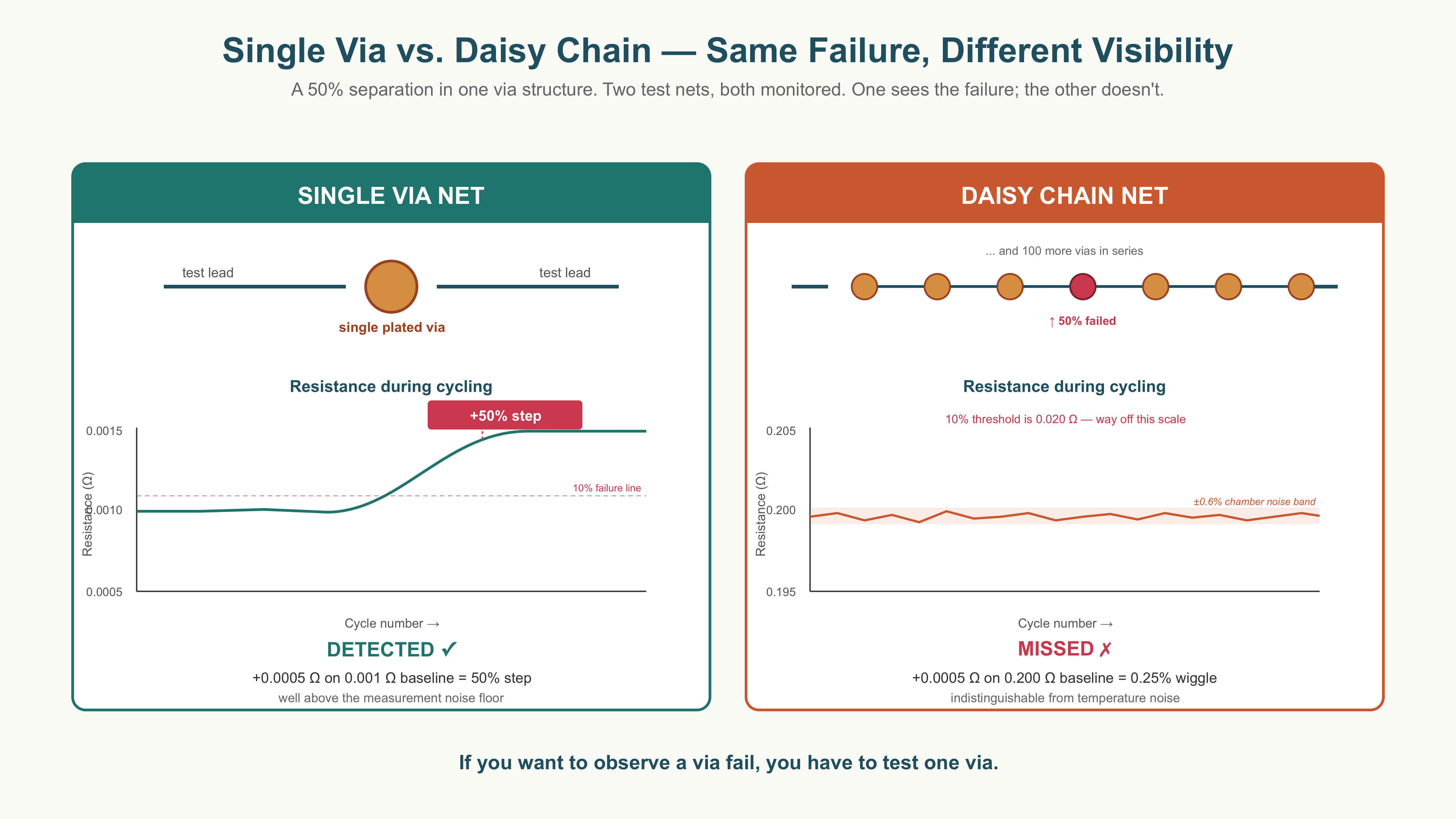
A typical single plated via structure has a resistance ~ 0.001 Ohms. In a 0.200 Ohm daisy-chain net, only 0.020 to 0.060 Ohms represents a plated via structure's resistance. A 10% crack/separation in ALL of the plated via structures at the same time, would only result in a 1 to 3% change in daisy-chain resistance and would not trigger a failure event. Even a 30% crack/separation in ALL the plated via structures in the daisy-chain at the same time would not exceed the typical 10% resistance change failure criteria for daisy-chain test nets. The assumption that all the plated via structures in a daisy-chain will fail at the same rate is highly unlikely and it would take a 95+% crack/separation of one or a few plated via structures to register a 10% failure change in the resistance of a typical daisy-chain of plated via structures. A 0.001 Ohm change in a 0.200 Ohm daisy-chain (representing an ~50+% crack/separation in 2-3 plated via structures), would read as a 0.5% change in total daisy-chain resistance, a value that would be seen as electrical noise or a slight shift in temperature of the test chamber and would not even be noted despite the significant degradation of some of the via structures.
Each 1°C change in temperature within a test chamber results in ~0.393% change in the electrical resistance of pure copper. Typical Shock/Cycling Chambers are rated at +/- 1.5°C which equates to 1.18% in electrical resistance variation just due to acceptable temperature tolerance within the test chamber which also hides these results in "noise".
It is clear that daisy-chains of plated via structures are only electrically sensitive to the end of a via structure's failure and cannot readily determine when a plated via structure begins its failure process. Daisy-chains certainly have their place in via structure reliability & robustness testing as they can determine when a plated via experiences complete failure, but the testing of single via structures is the only way to observe cracks / separations in plated via structures from their initiation through to failure.
Each Patented HATS² Single Via Coupon* contains 7 single via structure nets. These can be comprised of either the entire via structure or only portions of it (HDI, Buried, Between Subs) and allows isolation of problems to that area of the structure tested without needing to microsection. Each of these 7 Single Via structure nets can be changed into a short (~36 via) daisy-chain to allow a mix of single via structure and daisy-chain net data to be collected on the same test coupon. Testing 36 of these coupons in one HATS² Chamber load, you get a sampling of 252 nets of single via structures (or single via & daisy-chain) nets while being able to accurately track the initiation and progression of cracks/separation in each via while correlating to historical information with included daisy-chain nets.
The assumption that a Daisy-chain net has statistical significance to the PCBs it represents is basically inaccurate. To obtain "significance" from a sampling of via structures in a daisy-chain, mathematical models can be used with assumptions made regarding the similarity and variability within the population of via structures on the PCBs that the daisy-chain test coupon represents. As an example, for drilled via structures, a "similarly manufactured" population might be made up of 1200 via structures drilled by a single drill bit. To obtain a result confidence of 95% with a margin of error of 5%, 125 via structures from this one 1200 via drill bit population would need to be tested in the daisy-chain. Most PCB panels have many more than 1200 via structures and so this 125-structure sampling would need to be repeated for each set of 1200 "similarly manufactured" via structures on the production panel. This would require an unreasonably large daisy-chain coupon, manufactured in a way that represents the appropriate "significant" quantity of via structures from each population, which is not practical or feasible in most cases.
There are many issues with grouping "similarly manufactured" via structures to form a via population from which to calculate a statistically significant sampling size, but however you add it up, the numbers of via structures needed in a daisy-chain in order to get to a 95% confidence level of statistical significance is much higher than what is being tested today.
Results from daisy-chains without many hundreds of via structures in them have very low confidence statistical significance to the production panels they represent and are statistical "feel good" measures at best and at worst, could be hiding small increases in resistance indicating structural issues in the via structure. In addition, in order to test the high resistance associated with a large daisy-chain, the current flow through the daisy-chain must be reduced significantly to prevent circuit heating that would change the daisy-chain's resistance. This also affects the accuracy and significant digits of resistance measurement. A 50% crack or separation in a single via structure would go unnoticed as it would only register a change of <0.0005 Ohms in a daisy-chain resistance that might exceed 1 Ohm (0.05% change). Even if we had several via structures with a 50% crack or separation, their effect would only amount to noise in the measurements made.
Daisy-chains certainly have their place in via reliability and robustness testing to determine the endpoint of via structure failure, but single via structure testing is the only way to monitor cracks / separations in via structures from their initiation through to ultimate failure.
The HATS² Single Via Coupon* uses Patented Technology for Test Coupon designs. In order for a company to use this technology in their test coupon designs, they must sign a licensing agreement with the patent holder Reliability Assessment Solutions Inc. Licensing terms and fees will be determined on a case-by-case basis but will have reasonable and nondiscriminatory terms and conditions to applicants desiring to obtain such a license. To inquire about a license to use the Technology of the HATS² Single Via Coupon* please use the CONTACT US form in the Navigation Bar.
The Patented HATS² Single Via Coupon* contains 7 via structure nets. Each of these 7 via structure nets can be designed as either a single via structure, a portion of a via structure or daisy-chain nets to allow a mix of single via structure and daisy-chain data to be collected from each HATS² Single Via Coupon*. A single via structure (or portion of a via structure) net typically has a resistance less than 0.001 Ohms. Being able to measure percentage change at this very low resistance requires the ability to make accurate measurements below 0.0001 Ohms, a very challenging requirement which requires adaptation of both the test coupon and measurement system provided by the HATS² Test System.
Resistance of a single via structure must be pulled out of the total resistance of the entire test circuit which contains Test Lead Resistance, Resistance due to variation in temperature of the sample, Drift (Meter, Wire, Chamber Temperature) and finally the via structure's actual resistance.
HATS² Technology addresses Test Lead Resistance by using 4-wire Kelvin Techniques which determine the resistance of the test leads in both directions, leading to a more accurate accounting of the resistance of the test leads.
HATS² Technology addresses Drift by using 2 specialized circuits built into the surface of the Patented HATS² Single Via Coupon*. One of these circuits is >0.050 Ohms and one is <0.010 Ohms. By measuring these 2 circuits, a HATS² Test System can calculate Drift over time and remove it from measurements of Single Via Structure nets, giving a more accurate reporting of the net's value.
HATS and HATS² Thermal Shock/Cycling uses a HATS² Test System to perform Thermal Shock/Cycling in accordance with IPC-TM-650 method 2.6.7.2 and other industry Thermal Shock/Cycling test methodologies. The HATS² Test System uses High Speed “Air” as the heat transfer (fluid) mechanism to heat and cool the test coupons. This methodology changes the air volume in the test chamber surrounding the coupons several times each second. HATS² technology provides the maximum possible transfer rate to move heat through the test coupons using Air as a heat transfer mechanism. This changes the limiting thermal transfer factor from the test chamber to the coupon's mass and thermal conductivity. HATS² technology allows the test coupon core to equalize at temperature extremes in 3-6 minutes rather than the 30 minutes typically required by Dual Chamber and other technologies, greatly speeding up the testing process.
Test Coupon nets are electrically monitored (real time) in the HATS² Test System Chamber using a 4-wire test measurement sub-system to make accurate and repeatable resistance measurements of the via structures. This allows the HATS² Test System to determine barrel cracking or interconnection separations within the via structures. HATS² Test Systems can test up to 72 IPC-2221B "D" coupons (2 or 3 test nets each) or 36 Traditional HATS (4-nets), HATS² Single Via Coupons* (7-nets) or Custom 7-net coupons during Reflow Simulation and Thermal Shock/Cycling to determine barrel cracking or interconnection separations within the via structure.
The HATS² Test System most closely replicates the “Air” heat transfer mechanism of the widely accepted Dual Chamber technique that has been in use since the 1950s. Other High Speed Thermal Shock technologies use different heat transfer mechanisms like Oil, Liquid Nitrogen, Sand or Circuit Conduction Through Material to transfer heat to the coupons, which ultimately results in different heat transfer rates to and from the via structures under test than would occur using “Air". These differences can affect test results of the Via Structures under test. The HATS² Test System can test up to 252 nets (single via structure and daisy-chains) from a variety of industry accepted and custom test coupon styles using up to 7 test nets per coupon. Accomplishing Thermal Shock/Cycling of 1000 cycles with a full load of coupons can take weeks, if not months, using other "high speed" technologies due to their limited test coupon/net capacity when compared to the HATS² Test System. The HATS² Test system can accomplish 1000 Thermal Shock/Cycling cycles of 36 to 72 coupons in about a week. Carefully research the methodologies, their heat transfer mechanisms and their ultimate test net capacity before you decide on which technology is right for you.
In 2009, the PCB/automotive working group of the German Electrical and Electronic Manufacturers Association (ZVEI) published a method for testing single via structures during dual chamber thermal shock/cycling and much of the automotive industry has since adopted this methodology as a tool to determine via structure reliability. The resistance measuring technology found in the HATS² Test System builds on this established technique pioneered by this ZVEI working group.
Traditional HATS and IPC-2221B "D" Coupons are comprised of Daisy Chained via structures and can be electrically tested with other Thermal Shock/Cycling Technologies, including Dual Chamber. In addition to these widely used coupons, HATS² Test Systems can test HATS² Single Via & Custom test coupons* of up to 7 low resistance test nets which requires a unique measurement system to accurately measure resistances below 0.001 Ohm. Currently no other accelerated Thermal Shock/Cycling Technology can replicate the sensitivity, range and accuracy of the measurement capability found in the HATS² Test System.
The HATS² Test System uses High Speed Air as the heat transfer (fluid) mechanism to heat and cool the test coupons along with a sensitive 4-wire resistance measurement system that guarantees high accuracy testing of the via structure nets on the test coupons.
The HATS² Test System most closely replicates the "Air" heat transfer mechanism of the widely accepted Dual Chamber technique that has been in use since the 1950s. Other High Speed Thermal Shock technologies use different heat transfer fluid mechanisms like Oil, Liquid Nitrogen, Sand or Circuit Conduction Through Material to transfer heat to the coupons, which results in different heat transfer rates to and from the test coupon materials and via structures than would occur in Air. Other heat transfer mechanisms will affect the results from the via structures under test. The HATS² Test System can test up to 252 nets (single via structure and daisy-chain) from a variety of industry accepted and custom test coupon styles using up to 7 test nets each.
Accomplishing a Thermal Shock test of 1000 cycles with the volume of coupons/nets that the HATS² Test System can achieve in one chamber load can take weeks, if not months, using other "high speed" technologies due to their limited test coupon/net capacity and thermal transfer techniques when compared to the HATS² Test System. The HATS² Test System can accomplish 1000 Thermal Shock cycles of 36 to 72 coupons in about a week. Carefully research the methodologies, their heat transfer mechanisms and their ultimate test net capacity before you decide on which technology is right for you.
Understanding the mechanics of via structure failure is important to understanding the root cause of failure while implementing corrections to the manufacturing process. Knowing when your plated via structures begin to fail is important to determine robustness & reliability, evaluate material selection and implement process control. Being able to see the initiation point of a via structure beginning its failure using a Single-Via Structure rather than a daisy chain can enable a better understanding of differences in the manufacturing process while simplifying failure analysis by identifying the exact via structure where the failure occurred. As Via Structures have become more complicated and combine multiple technologies to form increasingly complex structures, having sensitivity to measure small resistance changes resulting from degradation in a part of a via structure is paramount to understanding the interaction with and failure mechanisms between connected structures within the Via.